![]()
|
|
|
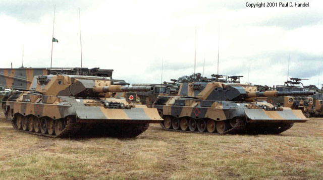
Two Leopard AS1 dozer tanks during a rehearsal for a parade in the mid 1980s. Both tanks are from Headquarters Squadron of the 1st Armoured Regiment, and carry the black Leopard head insignia on the turrets. The camouflage is mud over the original German green of the leopards when supplied to Australia. (leodoz04.jpg) |
![]()
The
introduction of the Leopard AS 1 Main Battle Tank into service with the Royal
Australian Armoured Corps in 1977 also saw the purchase of some training aids
and modification kits to allow the attachment of certain engineer devices
to the tanks. This article will look at the variations based on the Leopard Main
Battle Tank (MBT), and currently in use with the Australian Army.
![]()
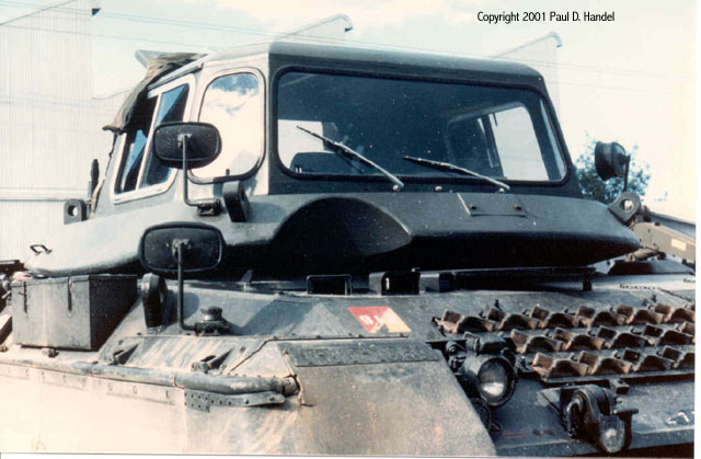
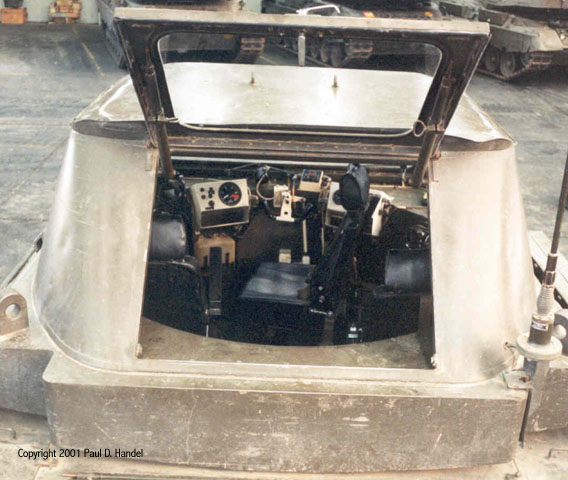
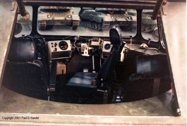
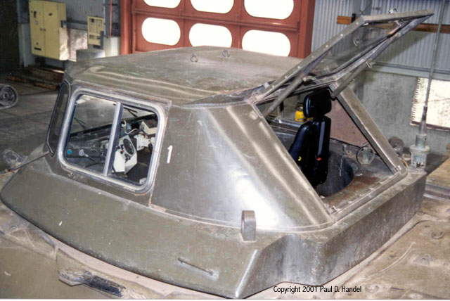
In order to gain maximum training benefit from the tanks, three driver training cabins were purchased for use within the Armoured Centre, now known as the Mounted Combat Division. These cabins replace the standard turret on a main battle tank. The normal turret is removed and placed on a stand, and this combination can then be used to train commanders, gunners and loaders in turret drills. In this way, two training aids are obtained for the price of one.
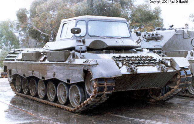
The
Driver Training Cabin comprises a cabin and ballast weight assembly which fits
into the turret ring of a standard MBT. It
is a non-rotating unit. A dummy gun
barrel can be fitted to the front of the cabin, to allow drivers to get used to
the overhang at the front of the tank. The
ballast weight is provided to allow the normal driving characteristics of an MBT
to be maintained. ( This was a problem with the locally constructed Centurion
Driver Training tanks – the removal of the turret without replacement of the
weight made the chassis rather more lively than the normal tank. )
The
cabin seats three personnel in comfortable high back seats with harnesses. The
instructor sits at the centre front, with one student on each side of him and
slightly to the rear. The
instructor has the ability to override the student driver using normal controls
for steering braking and acceleration. A repeater instrument panel allows
monitoring of the driver’s most important instruments – tachometer,
speedometer, etc.
The
cabin is provided with glass panels all around, including two sliding windows. A
rear lift - up glass doored hatch allows access to the cabin.
Windscreen wipers are fitted to the front window panel.
With
the Driver Training Turret fitted, the vehicle can still undertake fording
operations to allow the student driver to practice the necessary steps required
to prepare a tank for water entry.
In
Australian service, a tank fitted with this device is known as a “Cab Tank”.
Only the Mounted Combat Division uses these units in Australia.
Sometimes the cabins are fitted to MBT Dozer tanks.
![]()
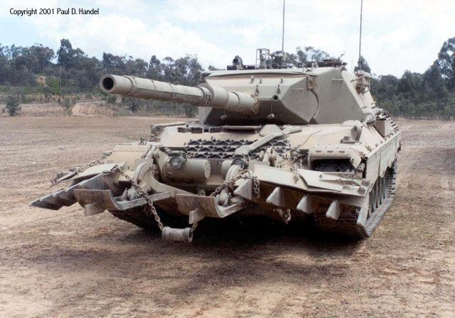
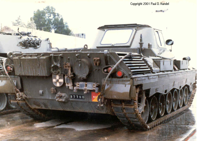
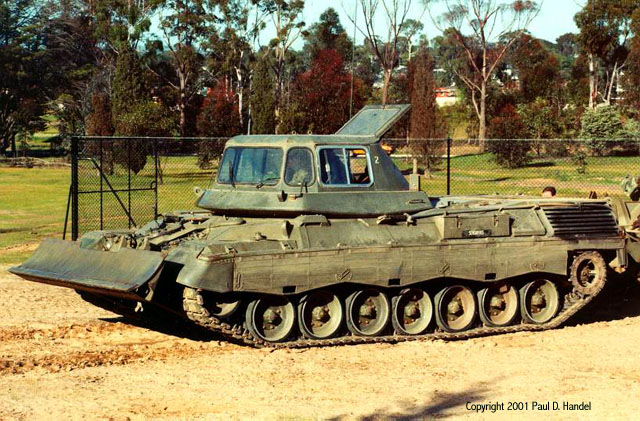
The purchase of Leopard AS1 included a dozer attachment
for the tank. This had not been
previously provided for Leopards, as the Leopard Armoured Engineer Vehicle, a
comprehensively equipped vehicle similar in looks to the Armoured Recovery
Vehicle (ARV), was used by most other armies.
The dozer attachment provided a blade, similar to that fitted to the ARV,
to be fitted to an MBT with minimal work. Tanks when fitted with the dozer
attachment are known as Medium Tank Dozer (MTD).
The dozer attachment consists of the dozer blade with two
push arms, two double-acting hydraulic cylinders and the bearing console
(a steel box-like unit) which has the necessary electrical and hydraulic
elements to operate the blade. The
blade’s operation is simply up and down, without angling or other operations.
The dozer attachment can be fitted to any MBT which has
the necessary short rails welded to the lower glacis plate. Originally the
electrical power connection was provided by the removal of one of the driver’s
periscopes and connecting the power cable to the slave start receptacle box in
the driver’s compartment. With
the purchase of mine clearing equipment and special interface kits, the
connection is now via an armoured cover and control box assembly mounted on the
left front of the upper hull.
The attachment is fixed to the hull by placing the lower
edge into the rails on the lower glacis plate and fixing the bearing console to
the hull via the standard tank towing lugs on the upper glacis plate.
An access cover on the bearing console allows the checking of hydraulic
oil levels and circuit breakers. Special
headlights are also fitted to the console, the tank’s standard lights being
removed.
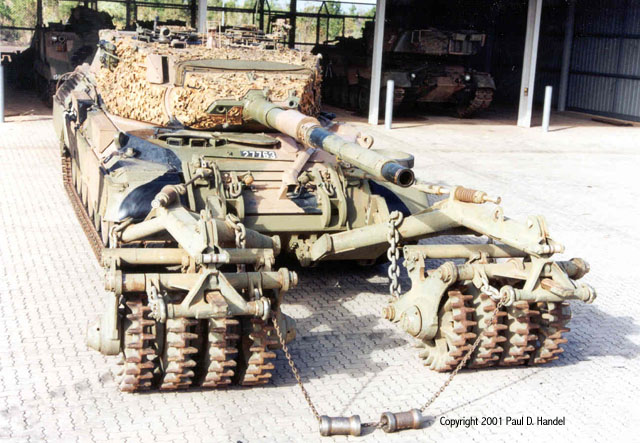
The attachment weighs around 2100 kg, and provides a blade width of 3250 mm. Raising and lowering of the blade takes about 10 seconds in each direction. The blade has no levelling function, therefore its usefulness depends upon the skill of the operator. The dozer is normally used for the construction of scrapes for tanks when in defensive positions, or for the preparation of entry/exit points on rivers, or for assisting the preparation of a suitable location for a bridgelayer tank during gap crossing operations.
![]()
The original purchase of
Leopard included an allowance for mine clearing tanks as part of the inventory,
but suitable equipment was not available at the time. In the early 1990s, an Australian team inspected the Track Width Mine Ploughs and Mine Clearing
Roller Systems with interface kits fitted to Canadian Leopard C1 tanks in
Germany, and then a Track Width Mine Plough fitted to a Centurion of the Israeli
Defence Force. Following these
inspections, the purchase of three Track Width Mine Ploughs and three Mine
Clearing Roller Systems from Israel, and fifteen interface kits from Krauss
Maffei in Germany was made. The
equipment entered service in 1993.
Tanks fitted with mine clearing equipment are collectively designated Medium Tank Mine Clearer (MTMC). The roller and plough tanks operate in conjunction with each other. The Mine Clearing Roller System (MCRS) is designed to be used when the presence of a minefield is suspected, but its exact location is not known. The rollers are used to “bump” the minefield and detonate mines on the edge of the minefield. When the presence of mines is confirmed by detonation, the tank with MCRS backs off and a tank equipped with Track Width Mine Ploughs (TWMPs) takes the lead and clears a lane through the minefield.
The Track Width Mine Plough unit (TWMP) was designed and
built by RAMTA, a division of Israel Aircraft Industries, and allows the
clearance of anti- personnel and anti-tank mines from the path of the tank
tracks. The plough action moves the mines aside without detonating them, and can
be adjusted to give a clearance depth of 200, 250 or 300 mm. The TWMP clears a
lane about one metre wide in front of each track, and there is an unploughed
lane 1500 mm wide between the tracks. In this uncleared area, the TWMP drags a “dog bone” which
is used to detonate tilt rod mines. The total weight of the installed equipment
is around 3 tonnes.
The TWMP comprises a main frame, which is attached to the
tank in a similar manner to the dozer attachment. Push beams provide support to the ploughs, known as
moldboards. Skids are located
on the push beams to regulate the plough depth. Lifting mechanisms allow the
left and right moldboards to be raised and lowered independently. An electrical
harness, feeding though the armoured conduit cover, connects with the control
box in the driver’s compartment. This provides the driver with the means of
operating the TWMP and also allows him to fire the quick disconnect cartridges,
which allows the whole assembly to be jettisoned in case of damage.
When originally purchased, the TWMPs were painted in
Israeli sand colour, and some of the photos show this.
Interestingly, the RAMTA company is located at Beer-Sheva in Israel,
better known in Australia as Beersheba, the location of the most famous of Light
Horse actions during the First World War.
One known experiment with the TWMP was soon after its introduction, when the Technical Squadron of 1st Armoured Regiment constructed a device to fit the TWMP allowing the clearance of scatterable mines. Although tested at the then Armoured Centre, it is believed to have been a unit experiment only. Two TWMPs are in service with the 1st Armoured Regiment and one with the Mounted Combat Division.
The Mine Clearance Roller System comprises a set of two
roller banks, attached to the front of an MBT, designed to detonate mines in the
path of the tank tracks. It is manufactured by Urdan Industries Ltd of Israel.
The design is very similar to former Soviet mine roller systems.
Each roller bank rolls a width of approximately 1100 mm
and there is an unrolled area of approximately 1500 mm between the rollers.
Mines buried up to 100mm deep can be exploded.
The total weight of the installed equipment is 9 tonnes.
The MCRS comprises a number of assemblies.
An adaptor plate is mounted onto the hull of the tank in a similar way to
the dozer and TWMP systems, using the hull rails and the towing lugs.
The adaptor plate mounts several brackets and tie rods. The roller bank
push arms are attached to the adaptor plate brackets. The roller bank push arms
have integral rubber buffers which allow deflection of the arms, via the pivot
when attached to the brackets of the adaptor, which can rise and touch the
adaptor during mine explosions.
The roller bank assemblies have four cast steel rollers,
the outside two of which are mounted on bearings, and the inside pair which have
a larger internal diameter and are free to move around the axle shaft.
The roller bank is attached to a pusharm via chains and trunnions.
Cable assemblies support the pusharms during normal
travel and absorb some shock during mine explosions. A dog-bone assembly is hung
between the two roller banks in order to detonate tilt rod mines.
The MCRS is a large and cumbersome device when fitted to the Leopard, and makes driving and steering somewhat sluggish. Their worth to mounted operations however, outweighs these factors, and their use by many armies around the world is proof of their effectiveness when dealing with minefields on the modern battlefield.
![]()
The author wishes to thank the officers and men of the (former) Armoured Centre and 1st Armoured Regiment for their co-operation over the last twenty or so years. Lieutenant Colonel Sam McPhee provided background details of the purchase of the mine clearing equipment and the photos of the Canadian and Israeli units in operation. Trooper David Gibson of the RAAC Museum clarified for me some of the details of the Driver Training Cabin from the user’s point of view.
![]()
|
A Leopard AS1 fitted with the Driver Training Cabin. Note how the ballast weight is scalloped to allow access to the driver’s hatch. (leodvr01.jpg) |
 |
A rear view of the same vehicle. The radio aerial mount on the rear right of the cabin can be seen. This photo was taken in 1980. (leodvr02.jpg) |
 |
A close up of the cabin front. The plate on the front with two bolts is the location for the dummy gun when fitted. Note the windsceen wipers and mirrors for the instructor. (leodvr03.jpg) |
 |
A rear view of the cabin with the rear hatch raised. The instructor’s seat has been swivelled to allow access, and the repeater instruments can be seen. (leodvr04.jpg) |
 |
A closer view of the previous photo. The driving controls, which override the standard tank controls can be seen. (leodvr05.jpg) |
 |
A left side raised view of the cabin, with rear hatch open. The sliding side windows can be seen . (leodvr06.jpg) |
 |
A combination Driver Training Cabin on the chassis of a Leopard AS1 fitted with a dozer attachment. Used for training purposes only. (leodvr07.jpg)
|
 |
The dozer attachment in the travelling position on a Leopard of the 1st Armoured Regiment. This is a rather pristine tank, shown in its original colours in this 1977 photo. (leodoz01.jpg) |
 |
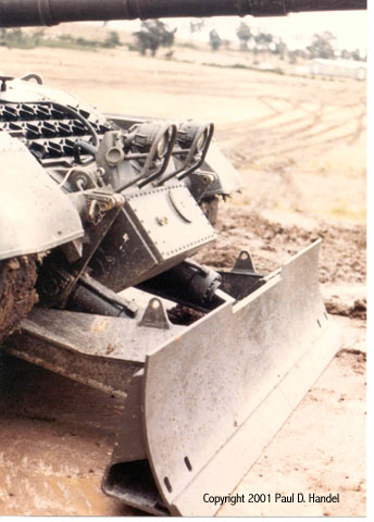
A dozer attachment with the blade lowered to the operating position. The bearing console, containing the hydraulic and electrical components sits in the centre of the glacis plate. The original control connection to the vehicle via the driver’s periscope can be seen in this 1978 photo. (leodoz02.jpg) |
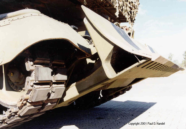 |
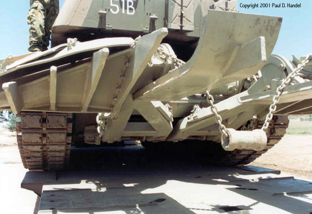
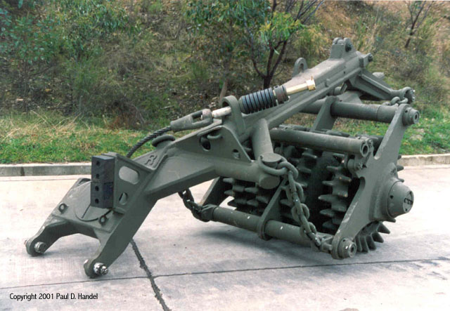
The push arms and the profile of the dozer blade are shown in this lower view of the unit in the raised (travelling) position. Note the brand new tracks fitted to this tank. (leodoz08.jpg) |
 |
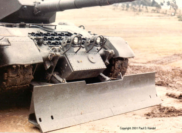
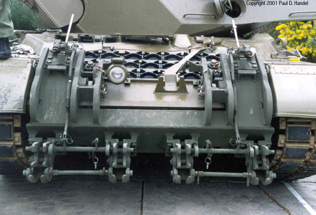
This view shows the hydraulic cylinders for blade actuation. The travel lock trunnions and pins can be seen, as well as the special headlights of the dozer attachment. (leodoz03.jpg) |
 |
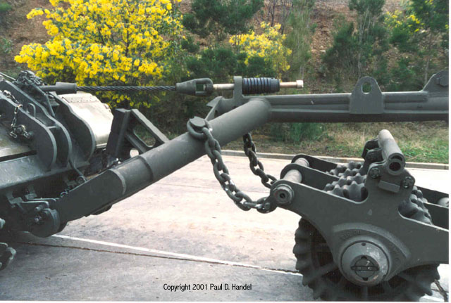
The right side of the lower glacis plate showing the rail for the mounting of the dozer and mine clearing attachments to Leopard AS1 tanks (leodoz05.jpg) |
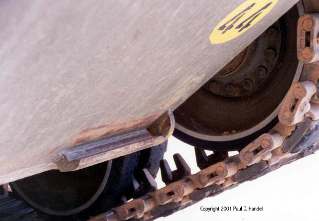 |
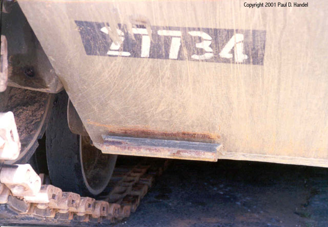
The left side of the lower glacis plate showing the mounting rail. Note how this rail differs from the right side rail, having an end stop. (leodoz06.jpg) |
|
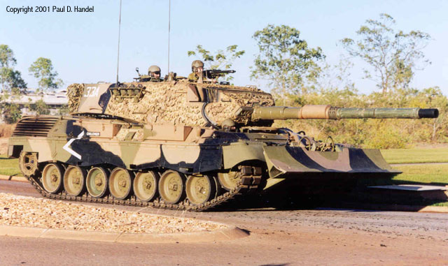
A Leopard AS1 with dozer attachment in three colour camouflage. Note the dozer blade has been camouflaged. The tank carries the Mobile Camouflage System (MCS) and the crew wear CVC helmets. (leodoz07.jpg) |
 |
A Canadian Leopard C1 fitted with the Mine Clearance Roller System being demonstrated to the Australian team in Germany. Photo by S.A. McPhee. (cdnmcrs.jpg) |
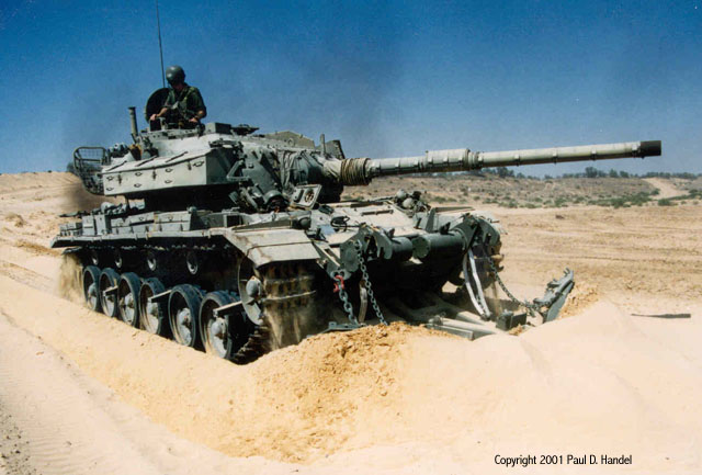 |
An Israeli Centurion fitted with Track Width Mine Plough operating in sand during a demonstration of its capabilities to the Australian investigation team. Photo by S.A. McPhee. (isrtwmp.jpg) |
|
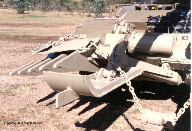
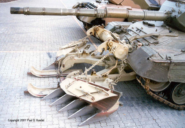
A Leopard AS1 fitted with TWMP. This unit is still in the original Israeli sand colour. The ploughs are in the travelling position and the extension boards are folded in. The dog bone is also in the raised position. (twmp05.jpg) |
 |
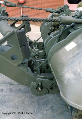
A close up of the right hand moldboard assembly and skid. The raising /lowering motor unit can be seen on the tank glacis plate. (twmp01.jpg) |
 |
A view of the push arms and moldboards from underneath. The skids are also clearly seen (twmp02.jpg) |
 |
The plough in the lowered position. The moldboard extensions are folded, and the skids rest on the ground. The armoured conduit cover to connect to the tank’s electrical is seen in position over the glacis plate. (twmp03.jpg) |
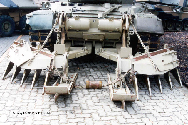 |
The same unit from the front, with details of the push arms and raising/lowering motors clearly visible. (twmp04.jpg) |
 |
The trial of a modification to the TWMP to allow clearance of scatterable mines. The mines are represented by boot polish tins taped together and paving bricks. (twmp08.jpg) |
 |
The adaptor plate for the MCRS attached to the glacis plate of an MBT. The brackets and link rods are in position. This is a brand new unit being fitted for the first time. (mcrs01.jpg) |
 |
The push arm and roller bank assembly ready for attachment to the adaptor plate brackets. Note the heavy construction of the unit. (mcrs02.jpg) |
 |
The above assembly installed on the tank. The cable with rubber buffers which supports each assembly during cross country travel can be seen. (mcrs03.jpg) |
 |
Details of the rubber bump stops and the connection of the roller banks and pusharms to the adaptor plate are shown in this view. (mcrs04,jpg) |
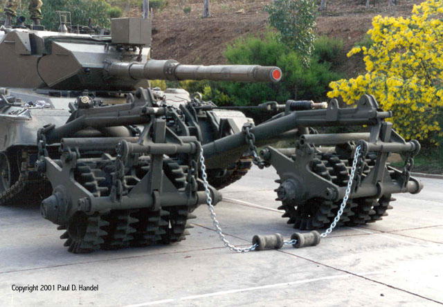 |
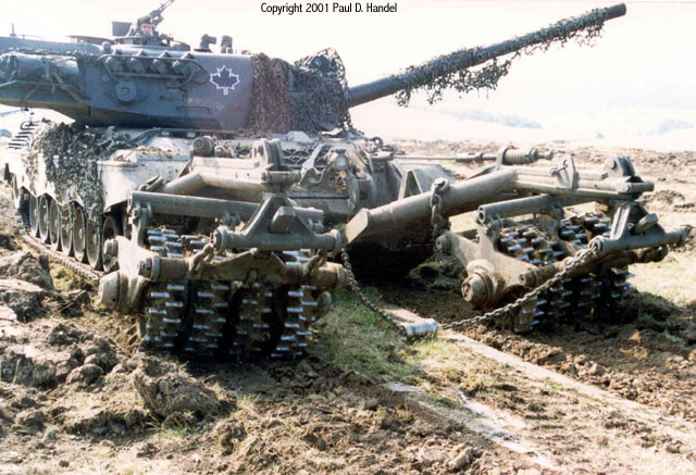
A view of the full MCRS assembly in the travelling position. (mcrs05.jpg) |
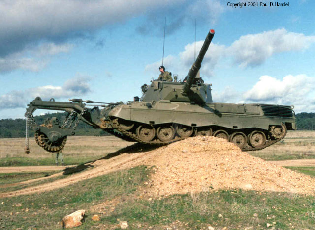 |
A Leopard with MCRS negotiating a vertical obstacle. Note how far in front of the tank the rollers protrude. (mcrs06.jpg) |
|
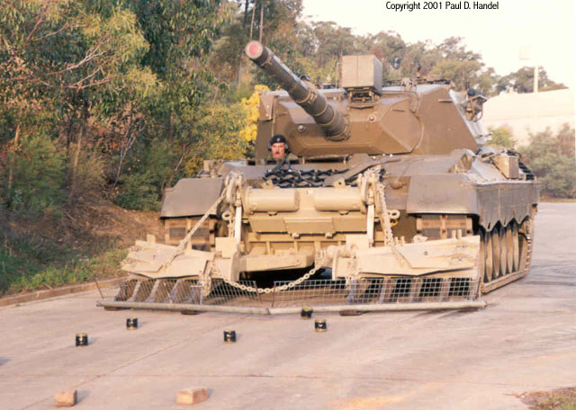
A Leopard AS1 with MCRS of the 1st Armoured Regiment. This slightly overhead view gives a good idea of the arrangement of the roller assemblies. The tank is fitted with the Mobile Camouflage System (mcrs07.jpg) |
![]()
Article Text and Photographs Copyright © 2000 by Paul D.
Handel
Page Created 25 August, 2001
Last Updated 05 June, 2001
Back to Anzac Steel Main Page