![]()
|
|
|
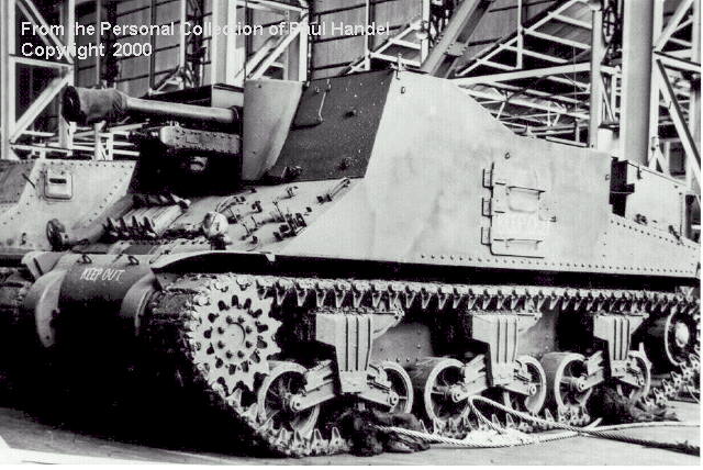
A Yeramba Self-Propelled Gun after completion at the Ordnance Factory Bendigo. The original part of the riveted Grant hull is visible, and a second Grant hull can be seen in the background, ready for conversion work to begin. The retention of the hull doors made ammunition resupply much easier than in the Sexton /Priest vehicles. |
![]()
As related in the previous article, there were a number of Australian modifications to the M3 Medium Tank series. Some of the major ones, which were either tested or reached production status, are described below. Even post war, a number of significant variants were still being used, giving the M3 Medium series a service life in the Australian Army of some 13 years.
![]()
Much developmental work was done for the wading of the Australian Army's Matilda and Grant diesel engined tanks. The Army's requirement was for the Grant to be able to wade to a depth of six feet (almost two metres). At least four different types of wading modifications were made to the Grants during 1944.
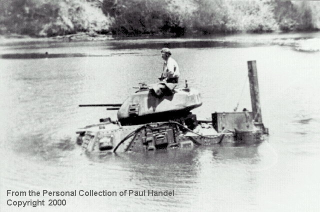
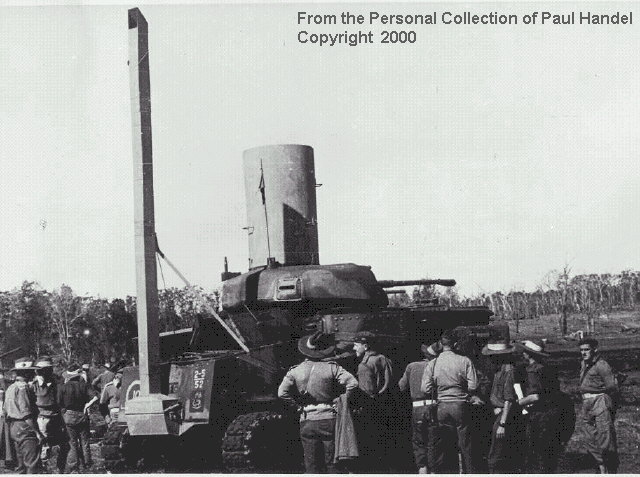
Early in 1944, the 4th Australian Armoured Brigade began a number of tests of tanks fitted for wading. An M3A5 Grant had its engine deck and exhaust outlet completely shrouded by a large structure of steel plates welded to the hull, whose height was greater than that of the turret. A small "conning tower", about 12 inches in height, was fitted over the commander's hatch. The Grant was able to wade to a depth of nine feet when fitted with this equipment, although its drawback was that it was virtually permanent in nature and the turret could not be fully traversed when the superstructure was fitted.
In August 1944, the 2/5th Australian Armoured Regiment made an exhaust stack and conning tower for an M3A5, and successfully waded the tank to a depth of 15 feet. The engine compartment was sealed off by fitting steel plates under the engine deck access doors and sealing them, with the engine air being drawn through the fighting compartment. A long conning tower was fitted over the commander's hatch. The tank itself was completely submerged during the test, and the crew remained inside for half an hour.
|
|
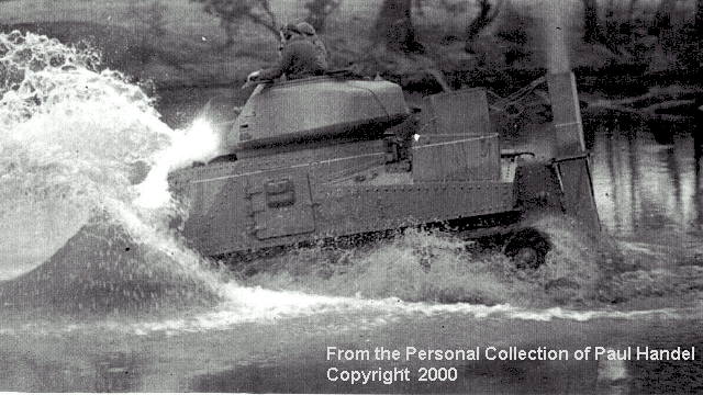
| A Grant making a high speed entry into the Goulburn river. The two short engine air intake and exhaust stacks are visible. Steel wire ropes support the stacks, and make the dropping of these devices after wading much easier. |
The next type provided for two ducts, one for the exhaust and one for the air intake. The ducts, built from hardwood, were similar in appearance to those fitted to US Shermans. The vehicle was trialed in six feet of water for 20 minutes without problems. The test was repeated six times, including a 100 mile road test. The work to seal the tank took about 50 man-hours. A quick release gear was fitted to allow the ducting to be dropped after the vehicle was on dry land.
A similar style of ducting, but without the turnovers at the top of the stacks was also tested, and proved satisfactory. This wading gear had an air inlet and exhaust stack but both were vertical units. Trials took place in the Goulburn River, near Puckapunyal, in September 1944.
![]()
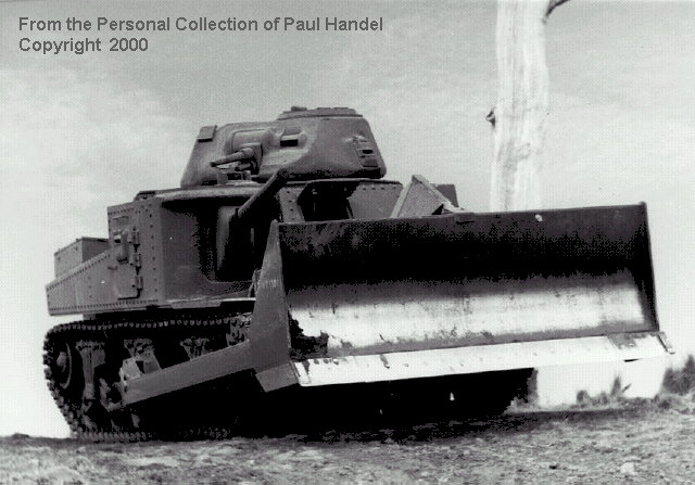
The dozer blade selected for mounting on the Grant was the same as fitted to the M4 Medium Tank, that is the M1 Dozer Blade built by the US Company La Plant Choate. The M3A5 GM Diesel engined Grant was chosen as the type of tank to be fitted as a dozer, and in common with many of the M3A5's in Australia in 1944, they were to be fitted with M4 Sherman suspension units, with trailing return rollers. These bogies could carry more weight than the M3 type, and were needed by Australian M3 Mediums at the time as a number modifications were being fitted, such as the applique armour on the nose, and the tanks' gross weight increased to a point where the heavier bogies were necessary. Also, in the case of the dozer, the M1 blade was designed to be fitted to the M4 Sherman suspension. It added about 4 tons to the vehicle gross weight.
The blade unit was 124 inches wide (cutting face) and had two arms which extended to the centre bogie unit of the tank on each side. The centre bogie was fitted with an adaptor plate on which the blade was hinged, and a projection from the adaptor plate was bolted to the front bogie of the vehicle. This provided a stable mounting for the blade arms.
|
|
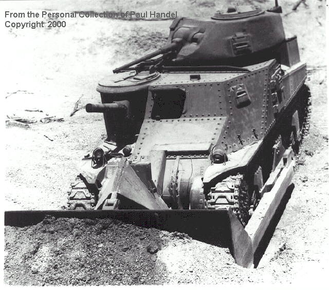
| An overhead view of the Grant Dozer during trials. The armoured protection for the hydraulic lifting cylinder (ram) and that for the hydraulic pipes leading into the hull can be seen. |
An oil pump driven by a power tank off from the tank's main drive shaft was fitted inside the vehicle, and this provided the hydraulic power. A single hydraulic ram provided the raising and lowering function. An armoured cover was fitted over the hydraulic ram and its hose connections. The base of the hydraulic ram was mounted on the lower part of the final drive housing and the ram end was connected to the centre of the blade in a tripod arrangement. A quick release pin was fitted to allow the ram to be disconnected from the blade.
The hydraulic piping from the ram ran up the final drive housing and entered the hull slightly above the final drive housing, through the blanked of apertures of the original hull machine guns. A fixed cover was mounted on the hull horizontally to cover the pipe, and a further hinged box protected the pipe over the final drive housing. The driver controlled the operation of the blade via a control valve.
As with dozer blade fitted the Sherman, manoeuvrability when using the blade was poor, due to the tank's steering system and its relatively long length of track on the ground. A Dozer Tank was extensively tested at the Proving Ground at Monegeetta in Victoria. The combination was officially designated Dozer, Grant III, (Aust.) No. 1 Mk1. They developed more power than the Matilda Dozers built around the same time, and thus were theoretically a better vehicle. Further tests were carried out by the 2/5th Armoured Regiment in the Wasp Creek area of southern Queensland in June, 1945.
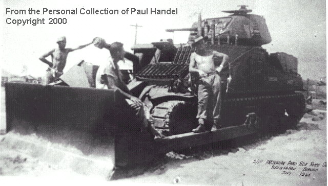
Three standard Grant M3A5 Tanks were included in the organisation of the 2/1st Australian Armoured Brigade Reconnaissance Squadron, a unit which operated the specialised armour of the 4th Australian Armoured Brigade. The three Grants were landed at Morotai in June 1945 during the build-up for the invasion of Borneo. The Brigade Commander received permission to fit them with M1 Dozer Blades, as their original function as armoured protection for Corps HQ was not to be utilised. The blades were fitted on Morotai in early July 1945, and the tanks subsequently were landed at Balikpapan.
As the opportunities for using the blades were found to be limited, shortly after landing they were removed. However one tank less blade was moved to the forward area on 19 July 1945 to support an infantry advance, but was not required. Thus the most numerous tank in the Australian arsenal during World War 2 was represented in a combat zone, although it did not fire any shots in anger.
Grant Dozers were kept on the strength of one of the Citizen Military Force (Reserve) Armoured Brigades after the war.
The Royal Australian Armoured Corps Memorial and Army Tank Museum at Puckapunyal in Victoria has an example of the Grant Dozer in its collection. This Grant exhibits a number of Australian modifications, such as armoured covers on the engine deck access doors, an upswept exhaust extension to facilitate the fitting of wading equipment and to divert the exhaust from raising clouds of dust, and of course the M4 suspension units. Recently, a set of anti-grenade meshing for the hull top was located and this has also been fitted to the vehicle.
![]()
By the middle of 1942 some 500 tanks had been received in Australia. Whilst maintenance support had been established and was growing with the formation of unit workshops and ordnance workshops, the process of recovery relied upon other gun tanks with tow ropes, or the few heavy tank transporters available.
It was therefore necessary to provide some vehicles capable of recovering knocked out or broken down tanks from the battlefield with a minimum of delay. The Australian Directorate of Armoured Fighting Vehicle Production (DAFVP) was tasked to produce a pilot model tank recovery vehicle based on an American M3 Medium Tank
The pilot model vehicle was constructed on an M3 Grant chassis, although all tanks so far seen in photographs were Lees.. The conversion to a recovery vehicle began by removing both the 37mm and 75mm guns and mantlets as well as the turret basket. The turret was fixed in position, facing the rear of the tank. The aperture in the turret created by the removal of the 37mm was covered by a hinged observation flap. An armoured, hinged door replaced the 75mm gun, and this provided better crew access into the hull.
|
|
| The ARV (Aust) No.3 with spade in the travelling position. The roller assembly is for guiding the auxiliary winch cable for the purposes of raising or lowering the spade. The vision port for use by the winch operator, and which replaced the 37mm gun mantlet, is open. |
The fighting compartment was gutted, and replaced by a winch unit. The winch unit was based around a grooved winch drum, 25 inches long and 17 inches in diameter, which accommodated 120 feet of 1 inch diameter steel wire rope. Power for the winch was provided by a Canadian-built Ford Mercury V8 engine, driving through a standard gearbox. The V8 engine was mounted in the left rear of the compartment, with the radiator drawing air via a shrouded fan. The winch drum was located approximately on the centre line of the turret, but towards the right side of the tank.
The winch rope was reeved directly down through the floor of the tank, passing around an idler drum which directed the rope to the rear of the vehicle. In order to anchor the tank when taking a pull with the winch, a spade was provided at the rear of the tank. This was made from heavy structural steel sections with six spikes to dig into the ground. The spade was pivoted on the idler lugs at the rear of the vehicle, and was raised and lowered by a hand-operated chain block.
The pilot model, originally known as Tank, Tank Recovery, and later as Armoured Recovery Vehicle (Aust) No.1, passed its preliminary tests in August 1942 and was despatched to the north of New South Wales to take part in manoeuvres with the 1st Australian Armoured Division. This division was at the time almost fully equipped with U.S. made M3 Light and M3 Medium tanks.
After successful testing had taken place, an order for 16 vehicles was received, later being increased to 24. The production vehicles apparently were all based on the M3 Medium Tank Lee, which was selected for conversion, as the Grant was preferred by the Australians as a fighting tank due to the placement of the radio in the turret as per British practice.
The first production model was not completed until late in April 1943, due to a hold up in the supply of components. The production models (later designated Armoured Recovery Vehicle (Aust.) No. 2) incorporated a number of improvements over the pilot model. An auxiliary winch with a capacity of 15cwt was built onto the main drive shaft leading from the reducer and this was used to raise and lower the anchor spade instead of the hand-operated chain block. The cable from the auxiliary winch drum ran up to the turret, out through the flap, over a roller frame assembly mounted on the rear deck and down to the spade. There it was reeved around a pulley and returned over the roller frame to the turret where it was fixed to the outside face. It was controlled by a dog clutch, which ensured that both winches could not be operated at the same time.
The winch was designed for a maximum single line direct pull of 28000 lbs. By passing the winch rope around a single sheave block, a pull of some 55000 lbs could be normally made. Subsequent testing showed a single line pull of 36,000 lbs at 55 feet per minute was possible.
Large stowage lockers were provided on the engine deck, running from the fighting compartment to the rear plate. These contained recovery equipment such as sheave blocks, shackles, auxiliary slings etc. A coaming was provided around the top of the barbette where the 75mm gun was originally mounted
During the early stages of the development of the production vehicles, an investigation was made to delete the Ford V8 winch engine and provide power to the reducer via a Power Take Off (PTO). This proved feasible and so it was decided that from vehicle number 7, this feature would be included. The only external difference of the model equipped with PTO was the deletion of the exhaust muffler for the Ford V8, located on the left side roof of the fighting compartment. Vehicles with power take offs were designated Armoured Recovery Vehicle (Aust) No. 3.
The first six production vehicles were completed by August 1943, and the 7th vehicle with PTO was completed in early September.
By this time the armoured division and other mechanised formations were being reduced, and the need for armoured vehicles was lessened as the Australian involvement in the war was directed towards jungle warfare. It would appear that the production of these vehicles did not proceed past the eight already produced.
One vehicle was taken to New Guinea in 1944 to undergo jungle trials. These trials concluded that although the armour protection was a decided advantage, the overall opinion of the vehicle was that it was unsuitable for jungle operations. The D8 tractor used by Australian armoured units in jungle warfare for tank recovery at that time was the preferred vehicle.
The vehicles were declared obsolescent in November 1944 and obsolete in 1946.
![]()
Attempts to procure self-propelled guns for training purposes from the United Kingdom proved unsuccessful during the immediate post-war period, and so an Australian project was initiated in July 1949 to convert a Grant III tank (M3A5) to the role of a self-propelled 25 Pounder gun. The Canadian Sexton self propelled gun, built on the Ram tank chassis which was very similar to the US Grant Tank chassis, was chosen as the model, and drawings were obtained from Canada and used as the basis for the design. The conversion of the Grant tank involved the removal of the turret and upper portion of the hull, and replacing this with an armour plated open topped fighting compartment. The side doors of the Grant were retained, which allowed easy access for the crew and loading of the ammunition, rather than over the sides as in a Sexton.
A fabricated bolster and beam assembly was welded to the hull of the vehicle, and this supported a saddle on which a 25 Pounder gun was mounted. The gun mounting, although similar to that of the ordinary towed gun, was strengthened and the pintle increased in size to withstand the recoil forces when rigidly mounted on the tank chassis. The recoil system was modified to limit the recoil of the gun to 20 inches (500mm). The 25 Pounder, was fitted with a muzzle brake and a counterweight near the breech. The mounting allowed an elevation of 40 degrees and a depression of almost 10 degrees. Traverse right and left of 20 degrees was possible before having to manoeuvre the vehicle. Standard 25 Pounder field gun sighting gear for both direct and indirect gun-laying was provided.
Ammunition lockers were provided on the rear bulkhead of the fighting compartment, and these could carry 88 High Explosive and/or Smoke shells and 16 Armour Piercing shells. Secondary armament was two Bren light machine guns, 2 Owen Machine Carbines, two .303 inch rifles and six hand grenades. The gun detachment comprised a commander, driver and four gun numbers. No seats other than for the driver and gun-layer were provided. A canvas canopy could be erected over the fighting compartment during inclement weather.
|
|
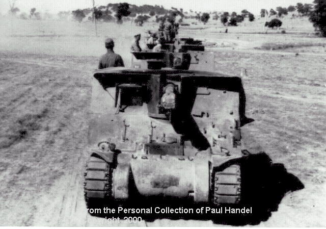
| A column of Yerambas of 22 Field Regiment (SP) on Puckapunyal range. No stowage is fitted, and the vehicle commander is standing immediately behind the driver's position, suggesting that the vehicles are on a driver training exercise. |
The driving controls of the tank were repositioned from the centre to the right side. A hatch, similar to the Grant drivers' hatch was provided, which contained a protectoscope for observation when closed down. A perspex window could be inserted into the open hatchway during adverse weather conditions. A sighting port was located in the left front hull plate. For communications purposes, a Wireless Set No. 19 Mk II (Aust) was mounted in the left rear of the fighting compartment. A cable reel was carried on the rear of the engine deck to allow signal line to be run between vehicles when firing as a Battery from static positions.
The Grant M3A5 chassis remained unaltered, except that M4 Sherman suspension units were fitted. Most Yerambas photographed in service mounted the Australian - made applique armour plate over the transmission housing.
The first unit was manufactured by the Development and Proving Establishment at Monegeetta, Victoria in 1949. After trials of the prototype, the Ordnance Factory Bendigo was awarded an order to build thirteen units. The first production model was delivered in November 1950, with the total order being completed early during 1952.
The equipment was known officially as "Ordnance, Quick Firing, 25 pr Mark 2/1, on Mounting Self Propelled 25 pr (AUST) Mark 1, on Carrier, Grant, Self Propelled 25 pr (AUST) Mark 1 ". The equipment became known in shortened form as the SP 25 pr Yeramba - the name "Yeramba" meaning "instrument for throwing spears".
The 22nd Field Regiment, a Victorian-based Royal Australian Artillery unit was equipped with Yerambas, and took the title of 22 Fd Regt (SP). They provided fire support to the Second Armoured Brigade during its annual camps at Puckapunyal.
The Yeramba had a short service life, being declared obsolete in 1956. It was at this time that all the World War 2 vintage M3 Medium Grants and the Matilda Infantry tanks were finally withdrawn from Australian service. A number of Yerambas have been known to survive, with the RAAC Tank Museum at Puckapunyal possessing a relatively complete example, but without the correct gun.
![]()
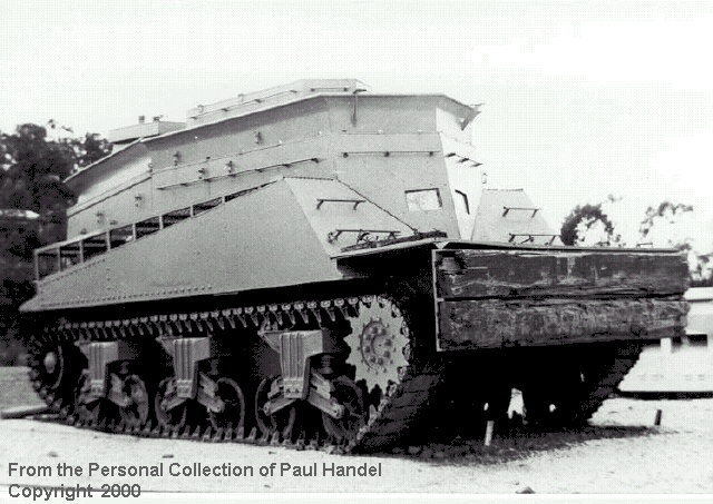
Successful amphibious assaults on the British beaches during the Normandy invasion in Europe in June 1944 was contributed to by the efficient Beach Landing Parties and Recovery organization which existed. The Beach Armoured Recovery Vehicle (BARV) had been developed by the REME on an M4A2 Sherman hull, and figured prominently in beach clearance during the Normandy landings. Some 52 vehicles had been produced by D-Day. The vehicle was designed to wade to the top of the coaming around the vehicle superstructure, and could either tow tanks off the beach, or using its nose plate push off landing craft that had become stranded.
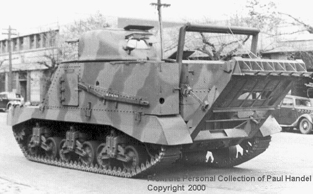
Authority was given in June 1949 for the Army Design Establishment to produce a conversion for the Grant tank into a BARV for training purposes. The turret and hull upper front and top were removed from an M3A5 (ARN 23893) and a wooden mock up superstructure was built. In early 1950, the go-ahead was given for the completion of the vehicle, and so the superstructure was rebuilt using ¼ inch mild steel plate. The superstructure was built generally along the lines of the British Sherman BARV, although a front upper hull following the Sherman's lines was constructed, obviously to allow the maximum use to be made of the British design. Two direct vision glass blocks were incorporated in the front of the superstructure. The rear of the superstructure, unlike that of the Sherman BARV, was flat.
|
|
|
Grant BARV |
Like all Grants serving with the Australian Army post war, it was fitted with the M4 Sherman suspension units.
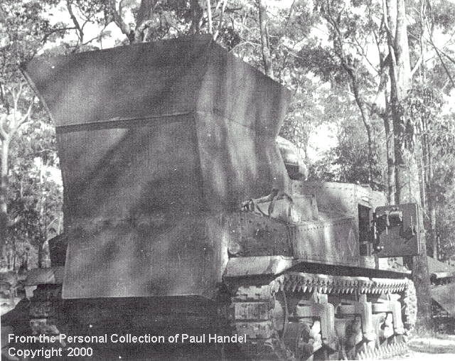
The modification allowed the BARV to operate in six feet of water with a three foot surf running. There was no winch fitted, the vehicle relying instead on tow ropes to move any drowned tanks. To allow connection of the tow ropes underwater, at least one crew member was trained as a shallow water diver. The front pusher plate mounted several railway sleepers and was designed to push landing craft off the beach if they became stranded.
The conversion was introduced into service as the Beach Armoured Recovery Vehicle (AUST) No.1 Mark 1. Only one vehicle was so converted. Issued to the Royal Australian Electrical and Mechanical Engineers Training Centre at Bandiana (RTC), Victoria, it did sterling work on courses and as a recovery training aid until 1970, when it was presented by RTC to the Armoured Centre, Puckapunyal to display in their then newly formed Museum. The Grant BARV still exists today in the collection of the RAAC Memorial and Army Tank Museum.
![]()
The various modifications of the M3 Medium Tank series made in Australia, either during or shortly after the Second World War, were not revolutionary, but were made using locally available material and equipment to meet a need that could not be serviced from overseas. Most of the modifications described in this article had already been made in other countries, specifically the United States or the United Kingdom, but nearly always on the M4 Medium Tank series. A number of photos of the M3 Mediums in Australia, including some of the conversions mentioned in this article, can be found in the collection of the Australian War Memorial.
![]()
The author wishes to thank Mr Walter Varley, OAM, of the 2/1st Armoured
Brigade Reconnaissance Squadron Association for the photo of the Grant Dozer on
Balikpapan in July 1945. Thanks are due to Mr Laurie Wright for his assistance
with the photos used to illustrate the article.
![]()
|
|
The wading Grant made by the 4th Australian Armoured Brigade, showing the welded steel structure over the complete engine compartment area. (grantwad3. Jpg) |
|
|
The wading Grant built by the 2/5th Australian Armoured Regiment. In this view the Grant is submerged only to about five feet in depth, and the exhaust stack only is fitted. (grantwad1.jpg) |
|
The same conversion after further modifications. The vertical exhaust stack is supported by several steel tie-bars, and the commander's cupola is fitted with a conning tower to allow observation by the tank commander during water operations. (grantwad2.jpg) |
|
|
The first Grant Dozer undergoing trials at the mechanisation Experimental Establishment. The blade is in the raised travelling position. (grantdoz1.jpg) |
|
|
A Grant Dozer on Balikpapan at the conclusion of hostilities. The grouser racks on the glacis plate are of interest. Various types of ammunition, located on the hull roof, are displayed by the crew. Photograph provided by Mr Walter Varley. |
|
|
A rear view of the Grant Dozer preserved at the RAAC Memorial and Army Tank Museum. Taken back in 1970, this view shows the blade mounted on M4 suspension units. This view also shows the upturned and protected exhaust duct and the additional armour on the engine deck doors. (grantdoz2.jpg) |
|
|
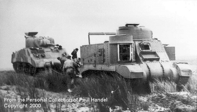
The early model ARV (Aust) No.2 winching the only M4A2 Sherman to arrive in Australia. The door in place of the 75mm gun is open, and the large rear stowage boxes are seen in this photo. (grantarv1.jpg) |
|
|
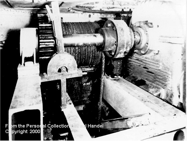
The interior of the prototype, showing the winch mounted on a frame, and the winch cable directed through the floor of the vehicle. The winch drive gearbox is seen on the right of the photo. (grantarv2.jpg) |
|
|
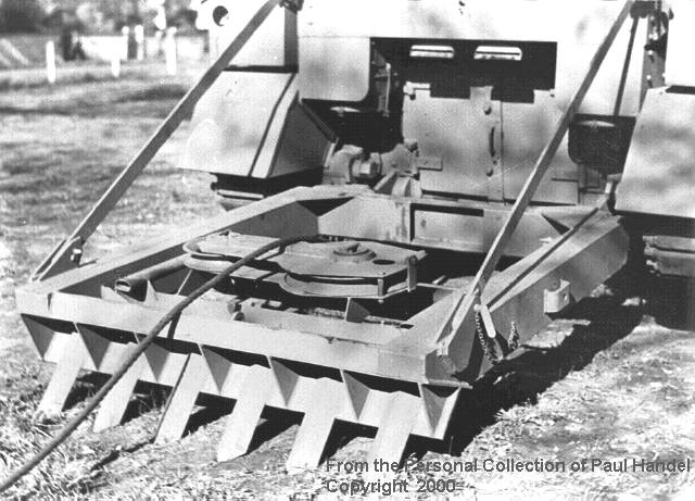
The heavy spade mounted on the rear of the vehicle in the working position. The snatch block, used for increasing the winch pull, is permanently mounted on the spade. The winch cable from under the vehicle is laying on the spade. (grantarv3.jpg) |
|
|
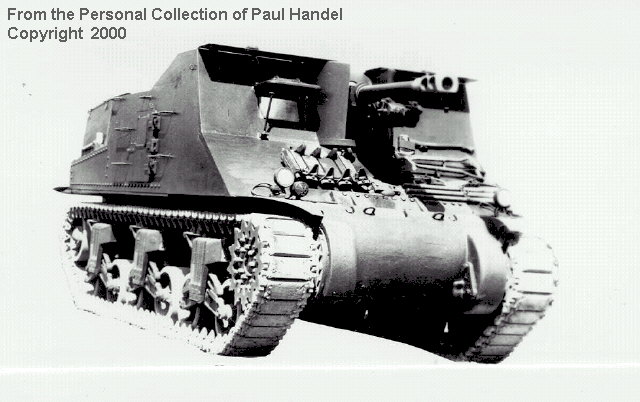
A fully stowed Yeramba. The M4 suspension units, and the applique armour over the differential housing are clearly seen. The additional shields over the driver's and gunner's positions are folded flat for travelling. (yeramba2.jpg) |
|
|
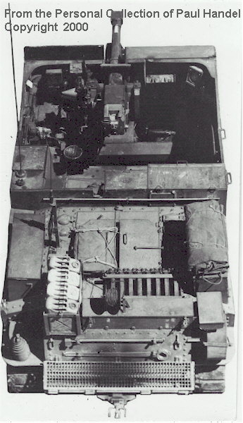
An overhead view of a fully stowed Yeramba. The upturned exhaust deflector with wire mesh protective panel is visible on the rear hull, and a spare vertical volute spring and roadwheel are stowed on the left and right rear trackguards. The telephone cable reel and jerrican rack, complete with US style jerricans, are mounted on the rear deck. (yeramba3.jpg) |
![]()
![]() Article Text and Photographs Copyright ©
2000 by Paul D. Handel
Article Text and Photographs Copyright ©
2000 by Paul D. Handel
Page Created 15 June, 2000
Last Updated 05 June, 2001
Back to Anzac Steel Main Page